Content
- The main advantages of standard solutions
- Problems of creating powerful wind power plants
- Properties of budget models
- Design features of high-speed systems
- Bicycle type generator
- Structural properties of the mast
- How to protect the windmill from hurricane wind?
- Recommendations for the manufacture of blades
- Arrangement of standard equipment
- Pantograph and mobile connection
- Battery-converter equipment
Compared to trendy photovoltaic sources of electricity, wind turbines may seem obsolete. In fact, this is far from the case. As the cost of traditional energy resources rises, new, more advanced and productive models with increased efficiency are being developed.
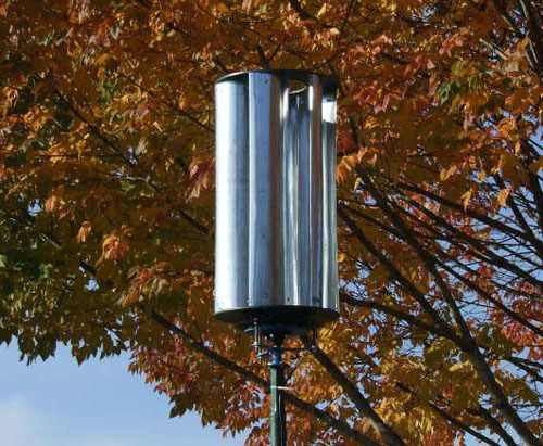
On sale, the cost of a household-class branded windmill starts at 2000 USD, but not everyone is satisfied with their technical characteristics. Many owners of remote households and summer cottages prefer to assemble a vertical wind generator with their own hands.
The main advantages of standard solutions
In the information field there are a large number of recommendations for the development of models of different capacities, taking into account the estimated costs, payback and planned load.
A branded wind power plant of an average power price range at a nominal wind speed of 5-6 m / s, produces up to 250 kilowatts of free energy per year.
If you create a vertical wind generator yourself, including from improvised materials, you will need several times less funds, which will positively affect the payback of the project as a whole.
On the other hand, the desire to implement a large-scale project for the construction of a powerful wind turbine to heat the house and operate energy-intensive household appliances will require significant costs. Let’s figure it out.
Problems of creating powerful wind power plants
The station with a power of only 2 kW is a strong wind-resistant structure installed in a massive concrete foundation with a height of 8 meters with a 3-meter metal rotor. In addition to the main costs, the installation of such a structure will require the cost of renting construction and crane equipment.
Attempts to assemble a more powerful vertical wind generator with your own hands without proper experience and a solid material base most often result in additional costs for fine-tuning the structure to working condition. For domestic use, at least at the initial stage, it is advisable to focus on creating a wind generator with a capacity of up to 500 watts.
Properties of budget models
For a home-made wind farm, it is recommended to take as a basis a design with a horizontal axis of rotation and a paddle impeller. Such schemes favorably differ in low material consumption and high efficiency. The most affordable and simple in design are high-speed two- and three-bladed wind turbines.
Design features of high-speed systems
The aerodynamic properties of high-speed rotors largely depend on the configuration of the blades. Outwardly imperceptible errors are reflected in the efficiency, therefore, without the lack of proper skills, it is better to give preference to the low-speed version of the impeller.
- The smaller the blades, the more problems with balancing the rotor. The optimal version of the wind wheel in terms of complexity and labor intensity with a diameter of 2 meters or more should have at least 5-6 blades.
- High-speed designs are characterized by increased noise, which increases with an increase in diameter and speed. This feature of a powerful high-speed wind power unit excludes its installation in areas with dense buildings or on the roof of an urban high-rise building.
Note: a twofold increase in the number of blades at a wind speed of 8 m / s. will help increase the generator power to 450-500 watts, but such a refinement will inevitably require the installation of an expensive gearbox.
Bicycle type generator
You can save money on the rejection of the gearbox by replacing the high-speed generator of the G-221 type with a slower-speed bicycle motor.
The presence of permanent magnets in the design of the bicycle motor solves the problems of supplying current to the excitation winding.
As a generator for a domestic wind power unit with a maximum speed of 220-230 rpm. it is enough to use a branded bike motor with a power of 250 watts. The efficiency of such a device is a little over 80%.
Structural properties of the mast
The starting material is a steel pipe with a diameter of 100 mm or more. The height of a mast with a solid concrete base installed in an open area can vary from 6 to 10 meters.
If there are buildings, trees or other windproof objects on the site, it is necessary to increase the height of the mast so that the impeller exceeds ground obstacles by at least one and a half to two meters.
For stretch marks, a mounting cable with a corrosion-resistant coating and a cross section of at least 6 mm is recommended.
How to protect a windmill from a hurricane?
In practice, a device that is simple in design and efficient in operation, known as a side shovel, has proven itself from the best side.
- With free stream speed up to 8 m/sec. the rotor is installed along its axis by means of plumage.
- When the wind intensifies, the flow pressure overcomes the stiffness of the spring and the wind generator folds, which leads to a change in the angle of air supply to the blades and a decrease in the level of perceived loads.
Blade Making Recommendations
For self-manufacturing of impeller blades, wood that is more resistant to tensile loads is more suitable. In a budgetary and less time-consuming option, PVC pipes with a diameter of 160 mm can be used as feedstock.
In the best solution, these are pipeline elements for pressure water supply and sewerage systems of the brand SDR PN 6.3 with a wall thickness of at least 4 mm. Plastic blades are less difficult to manufacture, less susceptible to temperature and humidity factors.
The workpieces cut according to the template should be carefully sanded and sharp edges rounded off.
Arrangement of standard equipment
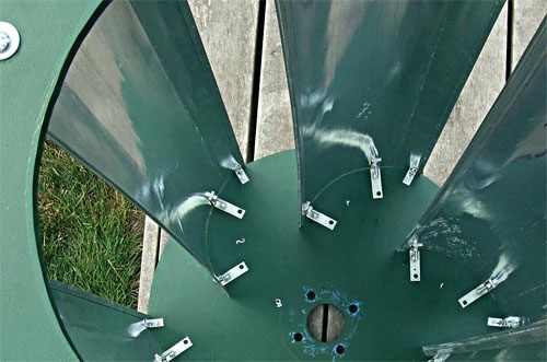
To attach the blades, you must use the head. The standard design is a steel disk 6-8 mm thick, to which, according to the number of blades, metal brackets 10-12 mm thick and 300 mm long with holes for installing threaded fasteners are welded at regular intervals.
The head is attached to the generator housing with locknut bolts. For the frame of the structure, steel with a thickness of 6-8 mm is required, or a sufficiently wide section of the channel.
Pantograph and movable connection
The design of the tandem moving contact-current collector is standard. In the simplest version, this is a dielectric bushing, a contact group and spring-loaded graphite brushes from a car starter. To protect against atmospheric precipitation, the unit is equipped with a protective cover.
To turn the rotor in the direction of the air flow, a movable connection of the wind generator frame is mounted in relation to the mast. Experts recommend using the advantages of the most resistant to axial loads roller bearings with a bore diameter of at least 60 mm.
Battery-converter equipment
The standard voltage of a bicycle motor generator is 25-26 volts, so two 12-volt batteries connected in series with a total capacity of 100 a / h can be used to store the generated electricity.
To convert direct current to alternating 220 volts, a voltage inverter with a power of 600 watts or more is introduced into the circuit.
Even if you can easily create a vertical wind generator with your own hands, remember that the trouble-free operation of such a device is guaranteed subject to timely and qualified service.
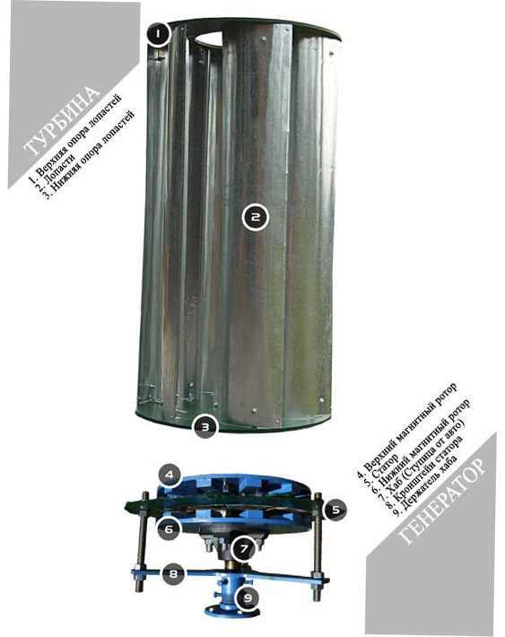
The sequence of steps for manufacturing a turbine:
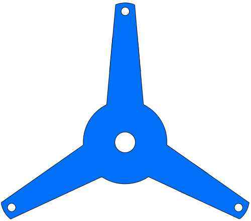
- Production of the lower and upper supports (bases) of the blades. Mark and use a jigsaw to cut out a circle from ABS plastic. Then circle it and cut out the second support. You should get two absolutely identical circles.
- In the center of one support, cut a hole with a diameter of 30 cm. This will be the top support of the blades.
- Take the hub (hub from the car) and mark and drill four holes on the bottom support for attaching the hub.
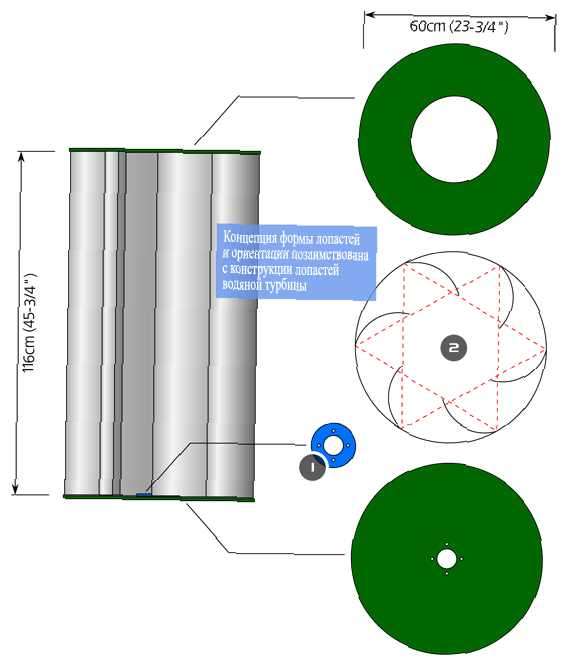
- Make a template for the location of the blades (fig. above) and mark on the lower support the attachment points for the corners that will connect the support and the blades.
- Stack the blades, tie them tightly and cut to the desired length. In this design, the blades are 116 cm long. The longer the blades, the more wind energy they receive, but the downside is instability in strong winds.
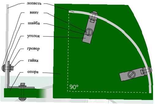
- Mark the blades for attaching the corners. Pierce and then drill holes in them.
- Using the paddle pattern shown in the picture above, attach the paddles to the support using the angle brackets.
Rotor manufacturing
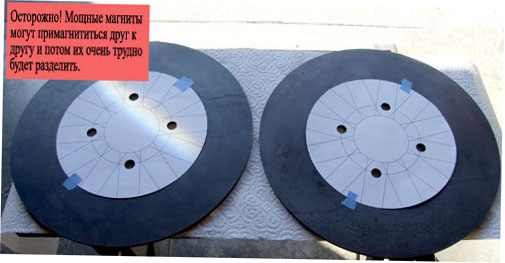
- Lay the two rotor bases on top of each other, align the holes and make a small mark on the sides with a file or marker. In the future, this will help to correctly orient them relative to each other.
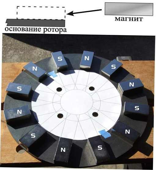
- Make two paper magnet placement templates and glue them to the bases.
- Mark the polarity of all magnets with a marker. As a «polarity tester» you can use a small magnet wrapped in a rag or electrical tape. By passing it over a large magnet, it will be clearly visible whether it is repelled or attracted.
- Prepare epoxy resin (by adding hardener to it). And apply it evenly on the bottom of the magnet.
- Very carefully bring the magnet to the edge of the rotor base and move it to its position. If the magnet is installed on top of the rotor, then the high power of the magnet can sharply magnetize it and it can break. And never stick your fingers or other body parts between two magnets or a magnet and iron. Neodymium magnets are very powerful!
- Continue gluing the magnets to the rotor (don’t forget to lubricate with epoxy), alternating their poles. If the magnets move under the influence of magnetic force, then use a piece of wood, placing it between them for insurance.
- After one rotor is finished, move on to the second. Using the mark you made earlier, position the magnets exactly opposite the first rotor, but in a different polarity.
- Put the rotors away from each other (so that they do not get magnetized, otherwise you will not pull it off later).
Stator manufacturing
The manufacture of a stator is a very laborious process. You can, of course, buy a ready-made stator (try to find them with us) or a generator, but it’s not a fact that they are suitable for a particular windmill with their own individual characteristics
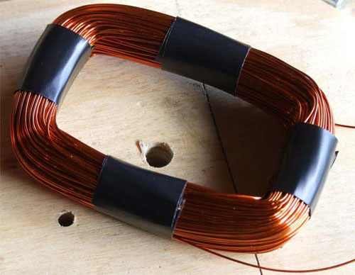
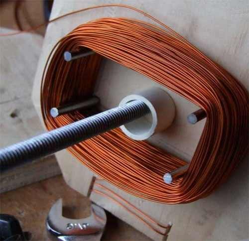
The wind generator stator is an electrical component consisting of 9 coils. The stator coil is shown in the photo above. The coils are divided into 3 groups, 3 coils in each group. Each coil is wound with 24AWG (0.51mm) wire and contains 320 turns. More turns but thinner wire will give higher voltage but less current. Therefore, the parameters of the coils can be changed, depending on what voltage you require at the output of the wind generator. The following table will help you decide:
320 turns, 0.51mm (24AWG) = 100V @ 120 rpm.
160 turns, 0.0508mm (16AWG) = 48V @ 140 rpm.
60 turns, 0.0571 mm (15AWG) = 24V @ 120 rpm.
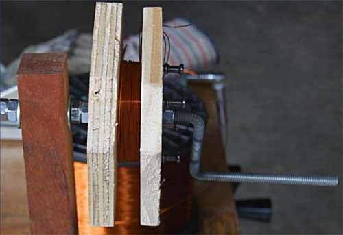
Winding coils by hand is a boring and difficult task. Therefore, in order to facilitate the winding process, I would advise you to make a simple device — a winding machine. Moreover, its design is quite simple and it can be made from improvised materials.
The turns of all coils must be wound in the same way, in the same direction, and pay attention or mark where the beginning and where the end of the coil is. To prevent unwinding of the coils, they are wrapped with electrical tape and smeared with epoxy.
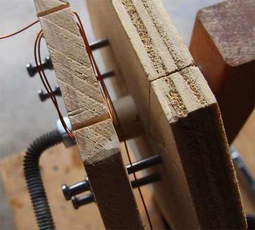
Coil winder
The fixture is made from two pieces of plywood, a bent hairpin, a piece of PVC pipe and nails. Before bending the hairpin, heat it with a torch.
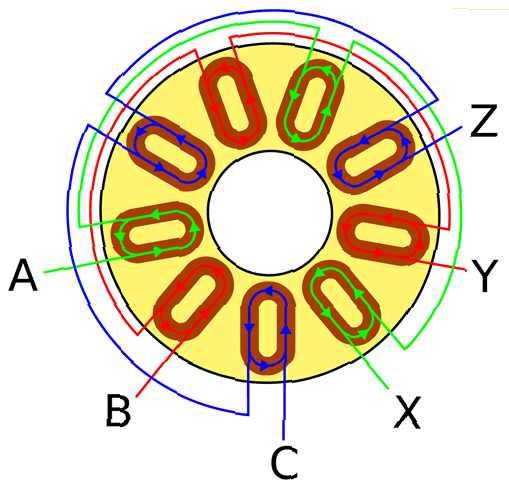
Connection diagram of stator coils
Do not connect household consumers directly from the wind turbine! Also observe the safety precautions when handling electricity!
Coil connection process:
- Sand the ends of the leads on each coil.
- Connect the coils as shown in the picture above. You should get 3 groups, 3 coils in each group. With this connection scheme, a three-phase alternating current will be obtained. Solder the ends of the coils, or use clamps.
- Choose from the following configurations:
A. Star configuration. In order to get a large output voltage, connect the X, Y and Z pins together.
B. Delta configuration. To get a high current, connect X to B, Y to C, Z to A.
C. In order to make it possible to change the configuration in the future, grow all six conductors and bring them out. - On a large sheet of paper, draw a diagram of the location and connection of the coils. All coils must be evenly distributed and match the location of the rotor magnets.
- Attach the spools with tape to the paper. Prepare epoxy resin with hardener for casting the stator.
- Use a paint brush to apply epoxy to fiberglass. If necessary, add small pieces of fiberglass. Do not fill the center of the coils to ensure sufficient cooling during operation. Try to avoid the formation of bubbles. The purpose of this operation is to secure the coils in place and flatten the stator, which will be located between the two rotors. The stator will not be a loaded node and will not rotate.
In order to make it more clear, consider the whole process in pictures:
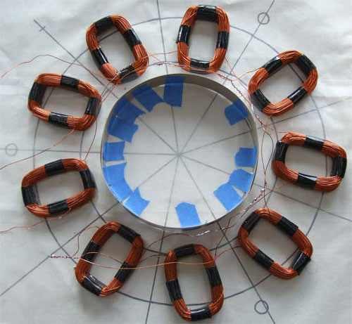
The finished coils are placed on waxed paper with the layout drawn. Three small circles in the corners in the photo above are the holes for mounting the stator bracket. The ring in the center prevents the epoxy from getting into the center circle.
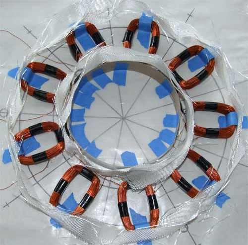
The coils are fixed in place. Fiberglass, in small pieces, is placed around the coils. The coil leads can be brought inside or outside the stator. Be sure to leave enough lead length. Be sure to double-check all connections and ring with a multimeter.
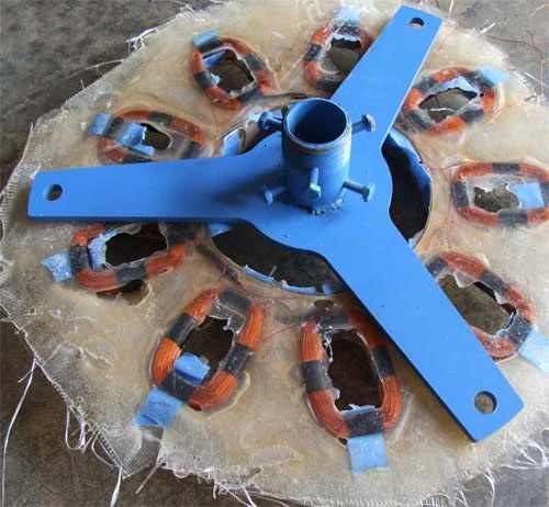
The stator is almost ready. The holes for mounting the bracket are drilled in the stator. When drilling holes, be careful not to hit the coil leads. After completing the operation, cut off the excess fiberglass and, if necessary, clean the surface of the stator with sandpaper.
stator bracket
The pipe for attaching the hub axle was cut to the desired size. Holes were drilled and threaded in it. In the future, bolts will be screwed into them that will hold the axle.
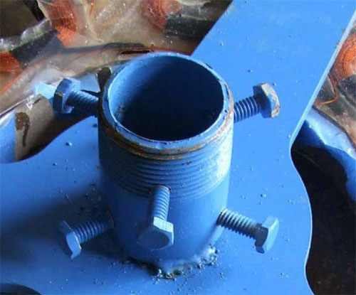
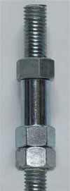
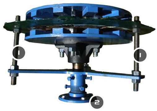
The photo above shows a stud with nuts and a sleeve. Four of these studs provide the necessary clearance between the rotors. Instead of a sleeve, you can use larger nuts, or you can cut washers from aluminum yourself.
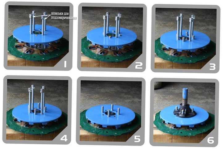
Generator. final assembly
A small clarification: a small air gap between the rotor-stator-rotor bundle (which is set by a pin with a bushing) provides a higher power output, but the risk of damage to the stator or rotor increases when the axis is misaligned, which can occur in strong winds.
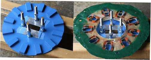
The left picture below shows a rotor with 4 clearance studs and two aluminum plates (which will be removed later).
The right picture shows the assembled and green painted stator in place.
Assembly process:
1. Drill 4 holes in the top rotor plate and thread them for the stud. This is necessary to smoothly lower the rotor into place. Rest 4 studs in the aluminum plates glued earlier and install the top rotor on the studs.
The rotors will be attracted to each other with a very large force, which is why such a device is needed. Immediately align the rotors relative to each other according to the marks on the ends set earlier.
2-4. Alternately rotating the studs with a wrench, evenly lower the rotor.
5. Once the rotor has rested against the bushing (providing clearance), unscrew the studs and remove the aluminum plates.
6. Install the hub (hub) and screw it on.
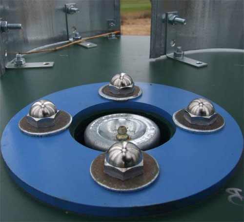
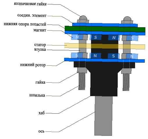
Cap nuts and washers are used to fasten the connections. boards and blade supports to the generator. So, the wind generator is fully assembled and ready for tests.
To begin with, it is best to spin the windmill with your hand and measure the parameters. If all three output terminals are shorted together, then the windmill should rotate very tightly. This can be used to stop the wind turbine for service or safety reasons.
A wind turbine can be used for more than just providing electricity to your home. For example, this instance is made so that the stator generates a large voltage, which is then used for heating.
The generator considered above produces a 3-phase voltage with different frequencies (depending on the strength of the wind), and for example, in Russia a single-phase 220-230V network is used, with a fixed network frequency of 50 Hz. This does not mean that this generator is not suitable for powering household appliances. Alternating current from this generator can be converted to direct current, with a fixed voltage. And direct current can already be used to power lamps, heat water, charge batteries, or a converter can be supplied to convert direct current to alternating current. But this is already beyond the scope of this article.
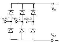
In the figure above, a simple circuit of a bridge rectifier, consisting of 6 diodes. It converts AC to DC.
Location of the wind generator
The wind generator described here is mounted on a 4-meter support on the edge of a mountain. The pipe flange, which is installed at the bottom of the generator, provides an easy and quick installation of the wind generator — it is enough to fasten 4 bolts. Although for reliability, it is better to weld.
Usually, horizontal wind turbines «like» when the wind blows from one direction, unlike vertical wind turbines, where due to the weather vane, they can turn and they do not care about the direction of the wind. Because Since this windmill is installed on the bank of a cliff, the wind there creates turbulent flows from different directions, which is not very effective for this design.
Another factor to consider when choosing a location is the strength of the wind. An archive of wind strength data for your area can be found on the Internet, although this will be very approximate, because. it all depends on the location.
Also, an anemometer (a device for measuring wind force) will help in choosing the location of the installation of the wind generator.
A little about the mechanics of the wind generator
As you know, the wind occurs due to the difference in temperature of the earth’s surface. When the wind rotates the turbines of a wind generator, it creates three forces: lifting, braking and impulse. The lifting force usually occurs over a convex surface and is a consequence of the pressure difference. The wind braking force occurs behind the blades of the wind generator, it is undesirable and slows down the windmill. The impulse force comes from the curved shape of the blades. When air molecules push the blades from behind, they have nowhere to go and they gather behind them. As a result, they push the blades in the direction of the wind. The greater the lifting and impulse forces and the less braking force, the faster the blades will rotate. Accordingly, the rotor rotates, which creates a magnetic field on the stator. As a result, electrical energy is generated.